DH Parameters
Denavit–Hartenberg Parameters
The Denavit–Hartenberg parameters (also called DH parameters) are the four parameters associated with a particular convention for attaching reference frames to the links of a spatial kinematic chain, or robot manipulator.
In this convention, coordinate frames are attached to the joints between two links such that one transformation is associated with the joint, [Z], and the second is associated with the link [X]. The coordinate transformations along a serial robot consisting of n links form the kinematics equations of the robot.
(In shorter words, you can create a transformation matrix of any kind by using just multiple rotations in the Z and X axis.)

Make sure to keep these rotations in mind


So what are these 4 values we're talking about anyway ?
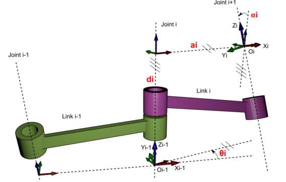
d : offset along previous z to the common normal.
Θ : angle about previous z, from old x to new x.
a : length of the common normal (do not confuse with 'α').
Assuming a revolute joint, this is the radius about previous z.
α : angle about common normal, from old z axis to new z axis
Woah! What happened?
I know it seems like we added lots of things in one go but let's take a step back and really think about what we just did.
Firstly, don't get confused by the fancy namings and the fancy notations. This stuff is nothing new.
Half of the DH parameters are barely the specs of the mechanical structure of the manipulator... AKA a and d are merely the lengths that the joints are occupying and the length of the links. Once these are measured, they never change again.
For the rest... Well it's not that easy anymore. Now we have to think about which rotations must be taken in order to go from one link to an other. Remember the previous page's training examples? Yes! You already did the most complicated part of DH parameters and you didn't even know it!
So again, let's think about how to rotate one link to the other using only X and Z axis rotations. And again, please don't forget the right-hand-rule, as it's most crucial here to keep consistent angles!
Cool but what do we do with the d and a parameters?
The purpose of these parameters is to understand how much to extend an axis in order to center the links so that our rotations aren't all done in one single point.
Now we need to be able to combines these rotations in the X and Z axis with their appropriate transformation matrices.
It is common to separate these displacement into the product of a pure translation along a line and a pure rotation about the line.


Now we can finally combine everything in one Translation matrix. Make sure to always keep this order as it's important to make sure to translate and rotate once we have positioned ourselves correctly in the reference frames.
Please keep in mind that rn is actually αn for our case.
Finally, combining the following matrices:


We get the Transformation matrix:

The bigger picture
Now that we know perfect how to get from one link to one link and keep the reference frames correct, we need to be able to combine all these and formulate one last formula for the whole manipulator.
Well there are good news and bad news... All we really need to do is to calculate the translation matrix shown above for each of the links, from link 0 to 1, from link 1 to 2, from 2 to ... you get the point. And after this all we need to do is to multiply them together! The good news is that these are all steps that we know how to do at this point, but it can be tedious to do this process many times, and that's the bad news. There isn't really a way around this problem.
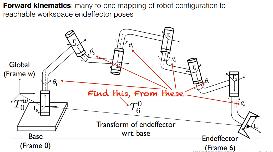
As you can see in the below picture, the main purpose of this convention is to find the forward kinematics, meaning that we find the location of the end-effector by understanding each angle and position of the joints and links.
Let's go through a couple examples together:
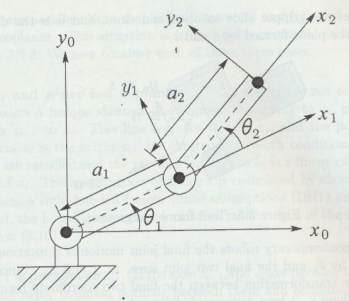
Let's start simple with a pretty simple 2 Degrees of freedom manipulator as shown below.
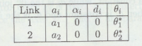
Now we need to create our DH table. We need to see which lengths matter for our case, and which angles the joints can move in.
As we can see, for this example, we ignore the offset between joints since we are only given a 2D representation. And have no information about the actual joint's displacements.
On the other hand we are given the lengths of the links which can be represented as a1 and a2.
We also don't have any information about the α angles because of the same reasons.
And finally, we care about the angles Θ1 and Θ2 which is the desired angles.
Let's create the DH table according to these informations:
Now we need to follow the same steps as previously shown:
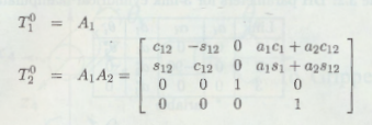
Doing this for each joint transformation we get:
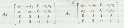
Finally computing the transformation matrix, first from joint 0 to 1, then from 0 to 2 combined:
I hope the previous example made sense, because the following example is more complicated as we add more information to the DH table because of the 3D representation of the manipulator, thus having more information given to us.
Take this following manipulator as example:
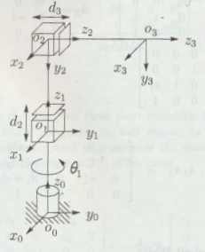
For this example, we can see that there is only one desired angle variable Θ1, but we can also observe that in order to go from joint 0 to 1, we need to translate the joint reference frame by a distance d1.
Now we're in the joint number 1's reference frame, if we wish to go from 1's reference to 2's reference frame, we need to again translate the frame by a distance d2 as shown, but we can also see that in order to achieve the 2nd joint's reference frame, we need to also rotate the X axis by -90 degrees.
Next, to go from joint 2 to end-effector 3, all we need to do is translate the reference frame by d3.
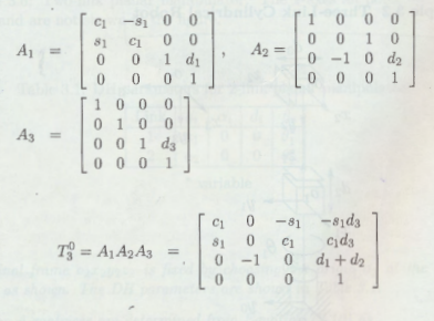
Cool! Now we have every information we need in order to create our DH table.

Now comes the easy and yet tedious part of calculating the transformation matrix.
I hope this made sense to you and feel free to practice a couple examples on your own in the next page!